Electric Condensate Recovery Unit

We adhere to customer-oriented principles and drive innovation through technology, providing comprehensive services from product selection to technical consultation, helping enterprises enhance steam system efficiency and create greater value.
Detailed Introduction
ELECTRIC CONDENSATION WATER RECOVERY DEVICE
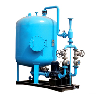
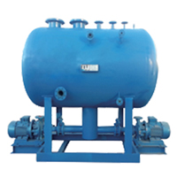
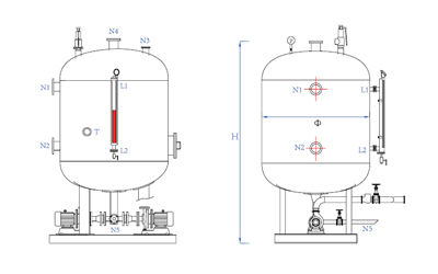
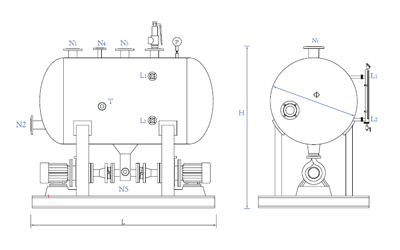
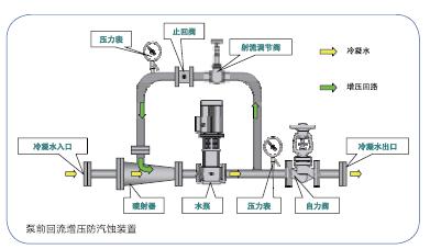
Electric condensate recovery device is arranged inside the tank water separation device, decontamination device, pressure regulating device, cavitation eliminating device, hydrophobic quick exhaust device; the lower part of the allocation of high temperature motor pump factory special; at the same time according to different working conditions, and is equipped with water vapor ejecting device, pump pressure device, low pressure conveying device, automatic pressurizing device etc. thus, completely closed recovery.
1. Automatic voltage regulator
North sparsely separates the equipment safety from the process safety, ensures the safety of the equipment structure with the safety valve, and ensures the safety of the production process by the pressure regulating device. In order to ensure the positive pressure head above 2m at the inlet of the pump, the automatic pressure regulating device is added in the water collector, and the principle of multistage water seal and "U" tube is adopted. The pressure adjusting device is divided into two kinds: one is no pressure, PN=0.01-0.09MPa, condensate recovery project commonly used in heating, refrigerating of central air conditioning in the 0.1Mpa below; a pressure type, PN=0.1-1.0MPa, commonly used in petrochemical, steel, thermal power and other industrial thermal system engineering. To ensure the normal return under the condition of pressure increasing, one is two times to two times the condensation of steam in the container, is an important energy saving measures of flash recovery; two is two times to the surface of the water vapor pressure, to ensure the pump pressure head required anti cavitation; three is the formation of a closed system, and ensure the equipment in the pipeline anaerobic, not rust.
2. Decontamination device
Condensate tank volume due to the volume of a container is smaller than the alternative catchment, early test of rust lump broken water pump impeller. Therefore, a decontamination device for oil pollution and impurities is added in the container to improve the pure purity of the water.
3. Cavitation elimination device
For many years, the water tank is placed above the pump to make the water pump get a static head to keep the water pump cavitation. The research and experiment show that the hydrostatic head exists in the static state, and the cavitation of the water pump occurs in the dynamic condition. Static and dynamic can not exist on the same equipment at the same time, so it is impossible to use static water head in static water to solve the cavitation of water pump in dynamic condition. The high water tank water to accelerate from a standstill to high speed flow in the pump (2950 RPM), rapidly shrinking flow section, high temperature water instantly under negative pressure evaporation, resulting in a large number of bubbles, the bubble burst into the pump pressure, the flow around the particle impact frequency was more than 20 thousand times per minute, in the extreme small area pressure often tens to hundreds of MPA, great mechanical damage to violent impeller, soon caused damage of impeller. The cavitation caused a sharp noise and a strong vibration.
When the water level in the centralized container descends to the bottom, there will be a precipitation funnel (the same shape as the tornado) on the original calm surface, and the cavitation of the two intake pump will still happen. According to the results of observation of transparent glass steel and water with deep color, with the spiral of Archimedes equation as the theoretical basis, the multilayer made of stainless steel by fluid, decline in water level, the upper guide structure to ensure the automatic locking, the low water level without "cavitation" phenomenon. The device is a cavitation elimination device.
4. steam water separation unit
Because the high temperature condensate is a two phase flow of steam and liquid, if it is not treated, it will lead to the suction pump and increase the cavitation of the pump. The two steam and part of the condensate water can be separated from the first part of the condensate by the built-in steam water separating device. The steam can be guided to the upper part of the recovered tank, and the two separated steam will form vapor liquid dynamic balance on the top of the tank. Then through the suction constant pressure device, the accumulated two steam and one steam is sucked, and the condensate of the pump outlet is transported to the next user.
Through the steam water separation device to ensure that the condensate is a single phase micro supercooled water at the moment of entering the pump, so as to eliminate the major cause of the cavitation of the water pump caused by the condensate.
5. pump modification
In order to meet the requirements of assembling two sets of motor pumps under the water collecting container, Beishu changed the existing single-stage pump. First, the water inlet pipe of the pump was changed from the original side to the top, and the water outlet pipe of the pump was changed from the original top to the side to form an ideal flow state. Second, the pump body was sealed mechanically, from the original temperature resistance of 80 ℃ - 110 ℃ to over 160 ℃, so as to enhance the temperature resistance and durability of the pump body. Third, the pump base was changed It is light weight and fixed directly on the channel steel under the equipment.
From the overall structure, it can be seen that the automatic pressure regulating device maintains the specific pressure in the collecting container. The condensate under the gravity and the two steam pressure, through the positive pressure pump of the cavitation elimination device, basically eliminates the condition of the high temperature condensate water to the pump cavitation.
6. Control system
The control system adopts variable frequency constant level control and continuous output of condensate water.
A, The condensate recovery device has PLC microcomputer control to realize the whole automatic operation of the device.
B The liquid level sensor sets four fixed level signal points from down to low, low, high, and super.
C The PLC microcomputer controls the pump automatically and intermittently according to the liquid level signal. That is to realize the high point to start the pump water, the low point to stop the operation of the pump, and to ensure the condensate to pump in time.
D The two pumps are operated automatically and regularly at one time, ensuring two pumps running at the same time. Each pump can operate two modes manually and automatically, and it can be converted freely.
E The control cabinet realizes the automatic protection and alarm for the overheating and overload of the pump. When a pump fails, another pump goes into operation automatically. The liquid level reaches the super high point automatically, and the other pump is started. The liquid level is lower than the ultra-low point, and the power is cut off automatically.
7. Steam absorption constant pressure device
In a closed recycling system, the traps are generally hydrophobic leak 3 - 5%, if not timely treatment will lead to the accumulation of steam leakage in tank pressure increases, thus the use of heat equipment back pressure, seriously affect the efficiency of heat transfer equipment, in fact many hydrophobic system leakage will be more, the pressure in the tank will rise even higher; multiple backwater together to tank due to the relatively high back pressure exists, will form a low pressure heat exchanger formation pressure, low pressure condensate due to poor drainage. The above two reasons will cause the use of thermal equipment to operate normally. When a closed system is running for a period of time, it has to drain the drain and the two steam, and turn the closed system into the open system, so as to ensure the normal operation of the thermal equipment. It is a great waste of energy.
In order to make the closed system with high leakage rate and hydrophobic multi-channel pressure ranging from condensate return to a recovery condition, ensure that the process of heat equipment and condensate recovery device normal operation, our company researchers developed a unique steam pressure setting device, it thoroughly solves the above the problem. Through the device, the pressure in the tank is lower than the inlet pressure of the condensate recovery unit, and the back pressure tank can be reduced to ensure the condensate output smoothly, without affecting the application effect of the hot equipment in the process and front-end.
8. low pressure conveyor
In the closed type condensed water recovery system, multi-channel to condensate recovery device, due to the relative pressure of the existence of low pressure high pressure condensate will form a mutual interference, low pressure condensate line formation pressure, causing hydrophobic sluggish, further influence the heat exchanger design front-end preparation. When a road network multi-path pressure is far lower than other road pressure, and the way the condensation of water and small, plus a waste recovery device; when the pressure is lower than 0.2MPa, and the hot spots are scattered, and the heat load is small, resulting in condensation of water pressure is very low, difficult recovery, mining and conveying device low pressure.
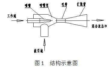
Working principle: our factory adopts a unique water water ejection device to transfer the low pressure condensate to the tank through the rheological diameter of the joint and the relative negative pressure produced. The device has high efficiency and good stability in order to solve the problem of poor water transport in low pressure pipeline.
9. pre pump booster
The condensate pressure produced in the first heat exchange system, heating and heat exchange system is very low, and it is closed recycling. When the pump starts and runs, the outlet of the tank will have relative negative pressure. The pressure of the pump inlet is smaller than the pump's cavitation allowance, and the pump will cavitation. The device can completely solve the problem and achieve complete closed recovery.
10. multichannel common network
It is used to return different pressure condensate back to the same pipe network or condensate recovery device to eliminate the mutual influence of all kinds of condensate water. By using the kinetic energy of high-pressure condensate, the pressure of condensate is balanced by the principle of suction, so that all kinds of pressure condensate can smoothly return to the network or condensate recovery unit. The equipment is a non standard equipment. The system is designed according to the water volume of the condensate per road and the pressure of condensate, so that it can be better adapted to the specific working conditions.
Simple installation, strong self-regulation, wide range of application.


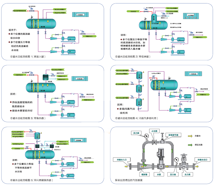
没有安装自力增压器水流示意图 安装了自力增压器后水流示意图
11. self powered turbocharger
After recovering steam from the condensate water generated by the thermal equipment, the recovery pipe often is bent underground or upwards, crossing the road obstacle and so on. When it is necessary to climb, the self pressurizing device is installed at the lowest part of the pipeline. With its special configuration to residual pressure of condensed water and two condensing energy release, improve the ability of the condensed water, eliminate water resistance, steam resistance and impact pipe etc.. The equipment is small in area, convenient to install, and does not need to increase any power source.
1) a demonstration of the effect of a supercharger and no supercharger in the condensate recovery system as shown in the following figure:
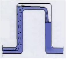
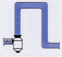
No water flow diagram of a self powered supercharger is installed Flow schematic after installing a self powered supercharger
Self booster role lies in the following two points: one is in the presence of water vapor only water does not go; two is to prevent the generation of steam resistance in the conduit top; three is the utilization of steam pipeline leakage and its flash vaporization pressure to push up condensate.
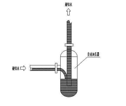
2) the working principle of self powered turbocharger:
This is independent of turbocharger working principle diagram, it can be seen from the figure, the vast majority of condensed water in the pipeline is half pipe water instead of water filled pipe, that is to say in the pipeline is the soda coexistence of steam in the upper water in the lower layer, in climbing at the pipeline system usually, usually pipeline the steam is before the water rises to the height, easy to form steam resistance on high, but in the pipeline to climb high installation of a self independent turbocharger turbocharger, general structure is the top outlet pipe extends to the bottom of the water is independent of the supercharger, walked up from the bottom, when the condensation of water and steam into the pressurizer, water in the supercharger bottom steam in the upper pressure of water, promote the condensation of water climbing, especially the driver of new steam trap leakage of the condensed water is larger, the upper part of the steam pressurizer through consumption, natural cooling, pipe work The function of the back pressure is also continuously condensed into water to be sent away.
Because the condensed water exists in the turbocharger expansion, so the turbocharger condensate pressure is higher than that in the supercharger before the condensed water pressure, in this respect also improves the condensate climb ability is the most important, it has a certain role in water vapor resistance, especially in the conduit closed system of steam resistance elimination effect is obvious. This is also one of the problems that must be taken into consideration in the closed system compared with the open system.
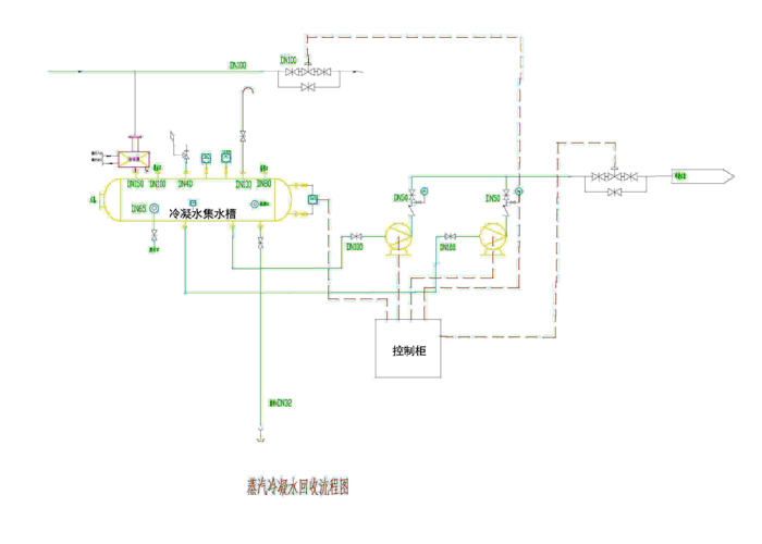
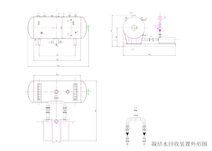
Electric condensate recovery flow chart